A voltage divider calculator helps anyone find the right resistor values or output voltage in a circuit with just a few clicks. This tool saves time and removes the guesswork from voltage calculations. Many beginners love how it makes designing a voltage divider simple, but experienced engineers also trust it for quick checks. They enter the known voltage, resistor values, or output voltage, then get instant results. For accurate circuit design, users should follow each step and double-check their voltage values.
Key Takeaways
-
A voltage divider calculator helps quickly find missing values like output voltage or resistor sizes, saving time and reducing errors.
-
The voltage divider formula splits input voltage based on resistor values, letting users control voltage precisely in circuits.
-
To use the calculator, enter any three known values (input voltage, R1, R2, or output voltage) with correct units, then calculate the unknown.
-
The calculator considers real-world factors like resistor tolerance and load effects, giving more accurate and reliable results.
-
Optimizing resistor choices and checking results with simulations improve circuit accuracy and prevent common design mistakes.
Voltage Divider Basics
What Is a Voltage Divider
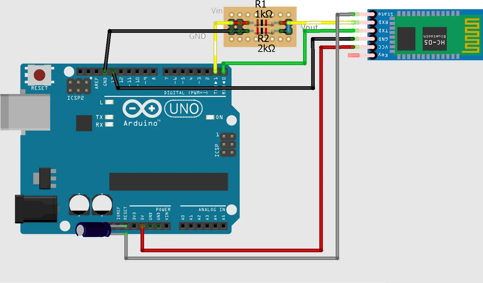
A voltage divider is a simple but powerful concept in electronics. It uses two resistors connected in series to split an input voltage into a smaller output voltage. Many electronics tutorials, like the one from SparkFun, show how a voltage divider works by using two resistors to divide the voltage. The voltage divider equation helps people figure out the output voltage based on the input voltage and the values of the resistors. This equation comes from Ohm’s law, which says that the voltage across a resistor equals the current times the resistance.
A voltage divider circuit lets users create a specific voltage from a larger supply. For example, someone might use a voltage divider to lower a 9V battery down to 3V for a sensor.
Paul Nicholls’ lesson on potential dividers explains that the voltage divider is not just about splitting voltage. It also teaches how the ratio of the resistors affects the output voltage. Students can see this in action with exercises and videos. The lesson covers real-world uses, like using a potentiometer as an adjustable voltage divider or connecting sensors such as LDRs and thermistors.
Why Use a Voltage Divider
People use a voltage divider because it makes controlling voltage easy. In a series circuit, the total voltage gets shared between the resistors. The same current flows through both resistors, and the voltage across each resistor depends on its value. This means the voltage divides in proportion to the resistors’ sizes. Engineers rely on this principle to design circuits that need a certain voltage at a specific point.
-
A voltage divider can:
-
Adjust signal levels for sensors
-
Create reference voltages for microcontrollers
-
Help with level shifting between different parts of a circuit
-
However, a voltage divider is not good for powering devices that need a lot of current. Tutorials warn that using a voltage divider as a power supply can waste energy and cause heat problems. Instead, people use it for low-power tasks where precise voltage control matters most.
Voltage Divider Formula
Key Variables
The voltage divider equation helps people figure out how much voltage appears across each resistor in a simple circuit. Three main variables play a role in this formula:
-
Vin (Input Voltage): This is the total voltage supplied to the circuit.
-
R1: The resistance of the first resistor.
-
R2: The resistance of the second resistor.
The voltage divider formula uses these variables to calculate the output voltage, which is the voltage across R2. The formula looks like this:
Vout = Vin × (R2 / (R1 + R2))
This equation shows that the output voltage depends on the ratio of R2 to the total resistance (R1 + R2). If someone increases R1 and keeps R2 the same, the output voltage drops. If they increase R2 and keep R1 the same, the output voltage rises. The voltage divider equation comes from Ohm’s Law, which says that voltage equals current times resistance. In a series circuit, the same current flows through both resistors, so the voltage divides based on their values.
Tip: The voltage divider formula works for any two resistors in series, no matter their size. It helps designers pick the right resistor values for their circuits.
How the Formula Works
The voltage divider equation makes it easy to predict how voltage splits in a circuit. When someone applies an input voltage across two resistors in series, the voltage divider formula tells them how much voltage appears at the point between the resistors. The key is the ratio R2 / (R1 + R2). This ratio decides what fraction of the input voltage shows up as the output voltage.
Let’s look at an example. Suppose Vin is 30 volts, R1 is 10 ohms, and R2 is 20 ohms. Plugging these into the voltage divider formula:
Vout = 30 × (20 / (10 + 20)) = 30 × (20 / 30) = 30 × 0.666... = 20 volts
So, the output voltage across R2 is 20 volts. This matches what the voltage divider equation predicts. The formula works because the voltage across each resistor in a series circuit is directly proportional to its resistance. Potentiometers use this principle, letting users adjust the resistance ratio and control the output voltage from a fixed supply.
The voltage divider formula is a powerful tool. It helps students, hobbyists, and engineers design circuits with the right voltage at the right spot. By understanding how the variables interact, anyone can use the voltage divider equation to solve real-world problems.
Using a Voltage Divider Calculator
Inputting Known Values
Getting started with a voltage divider calculator feels easy, even for beginners. The tool asks for four main parameters: input voltage, resistance 1 (R1), resistance 2 (R2), and output voltage. Users only need to know three of these values to find the fourth. Here’s a simple step-by-step guide:
-
Identify the four key parameters: input voltage, R1, R2, and output voltage.
-
Choose at least three values you already know.
-
Enter each value into the calculator, making sure to use the right units. Voltages go in volts (V), and resistances use ohms (Ω), kiloohms (kΩ), or megaohms (MΩ).
-
Double-check that all units match. Mixing units can cause errors.
-
Press the 'Calculate' button to let the calculator find the missing value.
-
Think about real-world factors like resistor tolerance, power rating, and how the load might affect your results.
-
Use the formula and example calculations provided by the calculator to understand how it works.
This process helps users avoid common mistakes and ensures the voltage divider calculator gives accurate results. The calculator’s design makes it easy to enter values, check units, and see instant answers.
Calculating the Unknown
The voltage divider calculator uses the classic formula:
Vout = Vin × (R2 / (R1 + R2))
This formula comes from Ohm’s Law and works for any two resistors in series. The calculator takes the three known values and solves for the fourth. For example, if someone enters the input voltage, R1, and R2, the calculator finds the output voltage. If the user enters the input voltage, output voltage, and R1, the calculator solves for R2.
The tool does more than just basic math. It considers real-world factors like resistor tolerance and load effects. For instance, if a circuit uses high-value resistors, the output voltage can drop when a load connects. Some calculators let users add load resistance to get a more accurate answer. This feature helps users see how the output voltage changes in real circuits, not just on paper.
Empirical data backs up the calculator’s reliability. Experiments and simulations show that the sum of voltage drops across resistors always matches the input voltage, no matter which resistor values are chosen. SPICE simulations confirm that the calculator handles different resistor inputs correctly. Technical reports also show that using the calculator to pick resistor values can reduce voltage divider error by over 60%. For example, choosing a 213kΩ resistor instead of a 210kΩ one can help avoid exceeding a reference voltage, leading to more precise circuit design.
Resetting the calculator and trying different values helps users find the best resistor combination. The tool can suggest several resistor sets that give the lowest output voltage error. This approach lets users optimize their circuit for accuracy and efficiency. By experimenting with different inputs, users can see how small changes affect the output voltage and pick the best design.
Interpreting Results
After the calculator finds the unknown value, users need to check if the answer makes sense for their circuit. The output voltage should match what the voltage divider formula predicts. Users can verify this by adding up the voltage drops across each resistor and making sure they equal the input voltage. This step follows Kirchhoff’s Voltage Law, which says the total voltage in a loop must be zero.
Practical examples help users see how the results work in real life. For instance, when connecting a sensor like a light-dependent resistor, the output voltage changes as the sensor’s resistance changes. The calculator shows how these changes affect the circuit. Potentiometers also let users adjust the output voltage, and the calculator’s results match what happens in the circuit.
Sometimes, connecting a device like a 555 timer can change the output voltage because of loading effects. Good calculators let users add load resistance to see this effect. This feature helps users design circuits that work as expected, even when connected to other devices.
Technical data shows that using a voltage divider calculator reduces calculation errors. For example, when using high-value resistors, the measured output voltage can drop if the load is not considered. Calculators that include load impedance give more accurate predictions. Experimental data also shows that the calculator helps users pick resistor values that match target voltage ratios, even when considering resistor tolerances. This makes the tool valuable for both learning and real-world circuit design.
Tip: Always double-check the calculator’s results with the actual circuit. Small differences can happen because of resistor tolerances or loading effects, but the calculator gives a strong starting point for accurate voltage divider design.
Practical Tips and Applications
Optimizing Your Circuit
Designers often want their voltage divider circuits to deliver stable and accurate output voltage. Choosing the right resistor values makes a big difference. When a voltage divider feeds an op-amp input, using very large resistors can increase noise and cause DC errors. These issues may degrade performance, especially in sensitive circuits. Large feedback resistors sometimes create stability problems by introducing phase shifts. To avoid these pitfalls, engineers check op-amp datasheets for recommended resistor ranges and use simulation tools like SPICE to test stability.
A good practice involves performing a tolerance analysis. This method checks how resistor tolerances affect the output voltage. For example, a ±1% resistor tolerance can shift the voltage divider’s output. By calculating the minimum and maximum possible output voltages, designers make sure the circuit meets accuracy requirements. Many engineers use Python scripts or calculators to automate these checks. Calibration also helps maintain accuracy over time, especially when temperature or aging might cause drift.
Performance improvements from optimization strategies show up in real numbers. The table below highlights some key benefits:
| Optimization Approach | Circuit/Application | Performance Metric | Improvement |
|---|---|---|---|
| Evolutionary Algorithms + Deep Neural Networks | General Analog/Digital Design | Design Time Reduction | 50% (halved) |
| AI Optimization | 45nm CMOS AI Chip | Power Consumption | Reduced from 50 mW to 40 mW |
| AI Optimization | Analog Amplifier for AI | Settling Time | 10% Faster |
| AI Optimization | General Circuits | PPA (Power, Performance, Area) | 20% Better |
Tip: Always check resistor values and simulate your voltage divider circuit before building. This step helps catch errors early and saves time.
Common Use Cases
Voltage dividers appear in many everyday and engineering applications. Here are some common uses:
-
Engineers use voltage dividers for signal level adjustment and biasing active devices in amplifiers.
-
Potentiometers act as adjustable voltage dividers in devices like radio volume controls and joysticks.
-
Designers measure sensor resistance, such as thermistors or RTDs, by feeding the divided voltage into a microcontroller’s ADC.
-
High voltage measurement uses resistor divider probes to safely scale down voltages up to 100 kV.
-
Voltage dividers help with level shifting, allowing low-voltage sensors to connect safely to higher-voltage microcontrollers.
-
They are not suitable as power supplies because of inefficiency and heat dissipation.
These examples show how the voltage divider remains a simple yet powerful tool in circuit design. Whether adjusting a radio’s volume or reading a sensor, the voltage divider helps engineers control voltage with precision.
A voltage divider calculator gives designers a fast way to predict voltage in circuits. Empirical studies show that voltage divider circuits behave as expected, matching calculated voltage drops every time. Users often try different resistor values to see how voltage changes, which helps them find the best balance between accuracy and power use.
-
Voltage divider calculators let users see how load changes affect voltage output.
-
Choosing the right resistor values improves voltage accuracy and efficiency.
-
Many users adjust resistor values to reduce power loss and improve measurement accuracy.
Experimenting with resistor values in the calculator helps users learn how voltage works in real circuits. This approach leads to better circuit design and fewer errors.
FAQ
How accurate are voltage divider calculators?
Most calculators give very accurate results for basic circuits. They use the standard voltage divider formula. Users should remember that real-world factors, like resistor tolerance and load, can cause small differences.
Can a voltage divider power a device?
A voltage divider works best for low-current applications. It cannot supply much current. If someone tries to power a device that needs a lot of current, the voltage may drop and the circuit may not work as expected.
What units should users enter for resistor values?
Users can enter resistor values in ohms (Ω), kiloohms (kΩ), or megaohms (MΩ). The calculator usually lets them pick the unit. Always check the unit before entering a value to avoid mistakes.
Why does the output voltage change when a load connects?
When a load connects to the output, it creates a parallel path with R2. This changes the total resistance and lowers the output voltage. Many calculators let users add load resistance to see this effect.
Written by Jack Elliott from AIChipLink.
AIChipLink, one of the fastest-growing global independent electronic components distributors in the world, offers millions of products from thousands of manufacturers, and many of our in-stock parts is available to ship same day.
We mainly source and distribute integrated circuit (IC) products of brands such as Broadcom, Microchip, Texas Instruments, Infineon, NXP, Analog Devices, Qualcomm, Intel, etc., which are widely used in communication & network, telecom, industrial control, new energy and automotive electronics.
Empowered by AI, Linked to the Future. Get started on AIChipLink.com and submit your RFQ online today!


